Week 06: Embedded Programming
Analog versus digital
While we have numerous states in an analog world, in a digital world there are always only two states. An example of this is the comparison between a joystick and a push button. An analog joystick can be moved in any direction and can thus assume numerous states. A digital push button can only have two states: on or off. In the digital world, there are always only two opposing states: On - Off, High - Low.
 By combining different states, we can create many more options.
The smallest unit of a state (switch) is called a bit. If we combine eight switches, we call it 1 byte. Since the switches can be combined in many different ways, 1 byte results in 256 options, namely 2^8 = 256.
In electronics, simplicity is defined by voltage. When the current is on, it's on, there's nothing in between.
Analog curves are round, while digital curves are angular because they can only represent two states. But the more information (bits) I have to draw a digital curve, the more the appearance approaches that of the analog curve.
By combining different states, we can create many more options.
The smallest unit of a state (switch) is called a bit. If we combine eight switches, we call it 1 byte. Since the switches can be combined in many different ways, 1 byte results in 256 options, namely 2^8 = 256.
In electronics, simplicity is defined by voltage. When the current is on, it's on, there's nothing in between.
Analog curves are round, while digital curves are angular because they can only represent two states. But the more information (bits) I have to draw a digital curve, the more the appearance approaches that of the analog curve.
Transistors and logical operations
Combinatorial vs. Sequential Transistors: with combinatorial transistors, the output depends on the input. With sequential transistors, the output not only depends on the input, but the output signal also influences the input again.
AND - NAND - OR - XOR are logical operations used to create logical connections between different input signals.
- AND: The output is true (1) only if both inputs are 1
- NAND: Negated AND function, the output is 0 only if both inputs are 1, all other combinations are true (1)
- OR: The output is true (1) if at least one input is 1
- XOR: The output is true (1) only if one input is 1.
There is not one better variant, but the best variant for a specific project. 3D files must always be converted to a mesh. We will typically work with STL or OBG. So, the model built in software must always be saved as STL. It is then converted into coordinates in a special software, in the slicer, so that it can be printed. The 3D printer works with coordinates. The process is always: Model - Slice - Printer. In the slicer software, we must specify which material we are using and with which machine we are working.
Mikrocontrollers
When selecting a microcontroller, we always have to ask ourselves what we want to do with it. How much processing power do I need? How much memory do I need? How much input and output? Are there libraries and support?
The following microcontrollers are used in the FabAcademy family:
- AtTiny: small, cheap, suitable for simple applications, UPDI programming (single-pin programming), Sandbox: Adrianino
- SAMD: programming is very complex with SWD/JTAG, High Hand Core, Native USB support, Sandbox board: Samdino
- RP2040 (Quentorres): even more powerful, created by Raspberry Pi, several pins, Programming: UF2, Sandbox: FabXIAO
- ESP32: also advanced microcontroller, Wi-Fi connection, Sandbox board: FabXIAO
- Assembly code: difficult to program, but the direct language for the microcontroller
- PIO: Very machine-oriented language, also very difficult to learn
- C and C++: Most microcontrollers are programmed with these languages, Arduino is based on C++.
- Rust: an emerging language gaining popularity
- MicroPython: Python for microcontrollers, Python is user-friendly.
- JavaScript: It is possible to use JavaScript on microcontrollers, but not as widespread as other languages.
- Mixed languages: It is possible to combine different languages
- Direct programming: The code is sent directly to the microcontroller via a cable
- Bootloader: A bootloader is on a microcontroller
- UF2: The microcontroller can be programmed via a USB connection
- Document your Code
- Always comment on what you are programming (to remember)
- Write modular and readable code
- Write parametrically (don't write too much directly into the code, so first define LED = 7 and then later only use LED, so that you only have to change LED = on another board)
All families are programmed differently. There are, of course, other microcontrollers (STM32, PIC, MSP/TI). General rule: Look at the datasheet for information.
You always need a language to program:
After you have written your code, you still need to send it to the micorcontroller:
Integrated Development Environment (IDE): is a software application that provides developers with a comprehensive set of tools to develop, test, and debug software.
Tips for programming:
Group assignment
On this page, you will find all the information regarding to our group assignment.
Programming with kids
I have decided to look into working with children on this topic again. And I looked for good tools to work with kids on microcontroller topics. I researched about the following programs:.
- Tinkercad: Tinkercad offers a great programming environment for circuits with simulation options for children. However, since I was looking for a way to work not only virtually, Tinkercad is not suitable for me in this case, as it does not offer the possibility to program a microcontroller, for example.
- Arduino IDE: Certainly, working with the Arduino IDE programming environment is also suitable for children. However, since my goal is to work with primary school children, the environment seemed too complicated for me.
- BlocklyDuino: The BlocklyDuino programming environment offers the possibility to work with code blocks. The visualization is similar to the visualization in Scratch and is therefore easier to understand and grasp for children. The environment seems to be a good option, especially if the children can speak English. Since my daughter cannot speak English, I did not test the environment together with her.
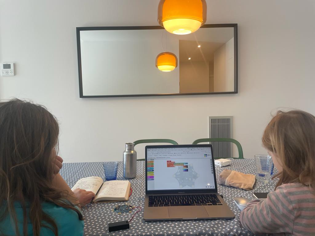
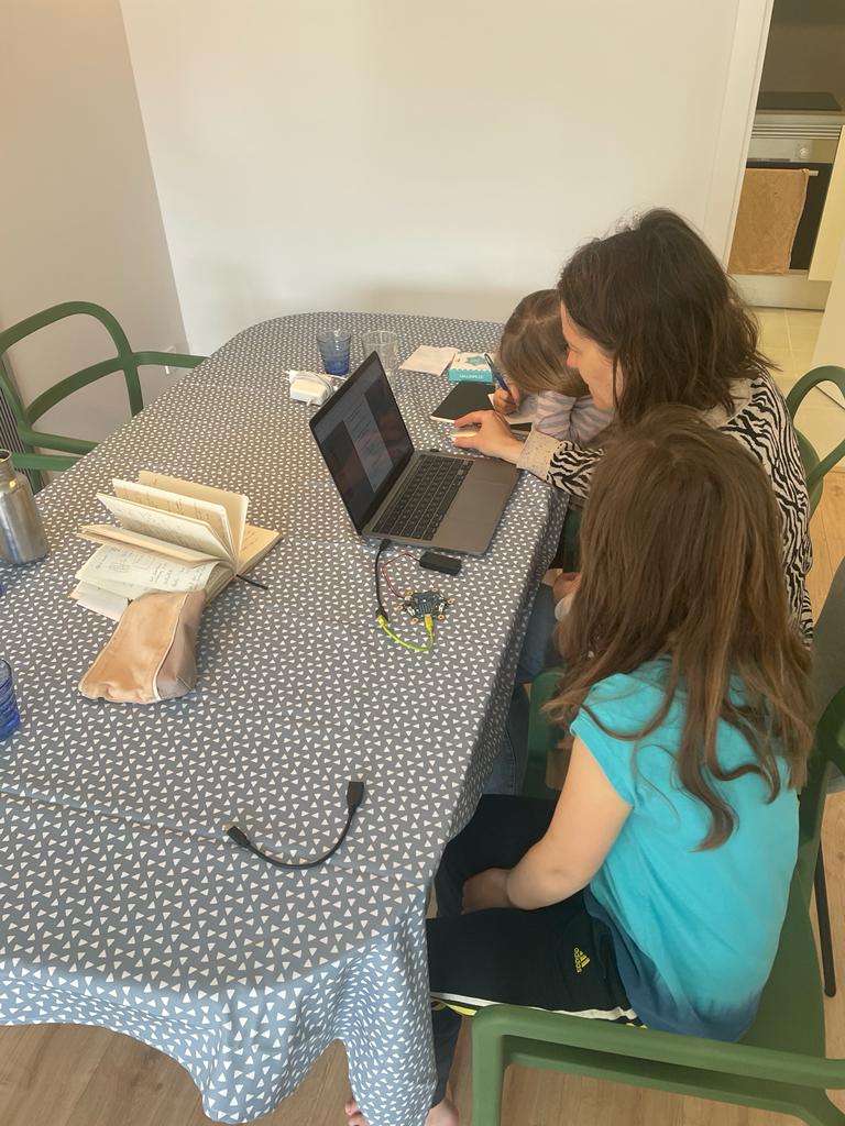
- Calliope mini and Open Roberta Lab: Since I have used the Calliope mini microcontroller in the past, I decided to work with it. I read up on it again first. The children's idea was to program a night light that turns on whenever the room gets dark. Using the example of an electronic thermometer that measures human temperature through the temperature sensor and then outputs a color signal (red for fever, orange for elevated temperature, green for normal temperature), I explained to the children what microcontrollers are and how they work. We then looked at the Calliope mini together and found the light sensor and LED. Then we opened Open Roberta and started programming the Calliope.
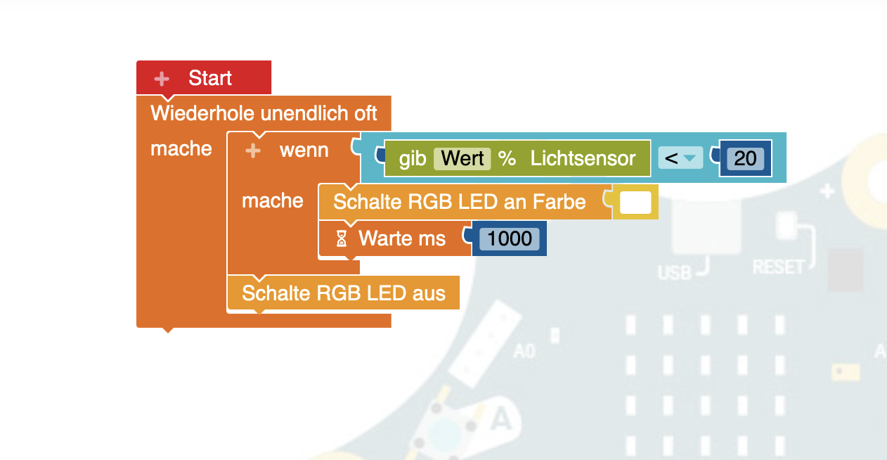
Similar to Scratch, Open Roberta works with colored blocks. We put together the following blocks:
- Kontrolle: Wiederhole unendlich oft (Control: Repeat infinitely)
- Kontrolle: Wenn … mache (Control: If... then)
- Logik: Wenn kleiner (Logic: If less)
- Sensor: Lichtsensor (Sensor: Light sensor)
- Wert: Kleiner als 20% (Value: Less than 20%)
- Aktionen: Schalte LED an Farbei „weiß“ (Actions: Turn LED on in white)
- Kontrolle: Warte ms 1000 (Control: Wait ms 1000)
- Aktion: Schalte RGB LED aus (Action: Turn RGB LED off)
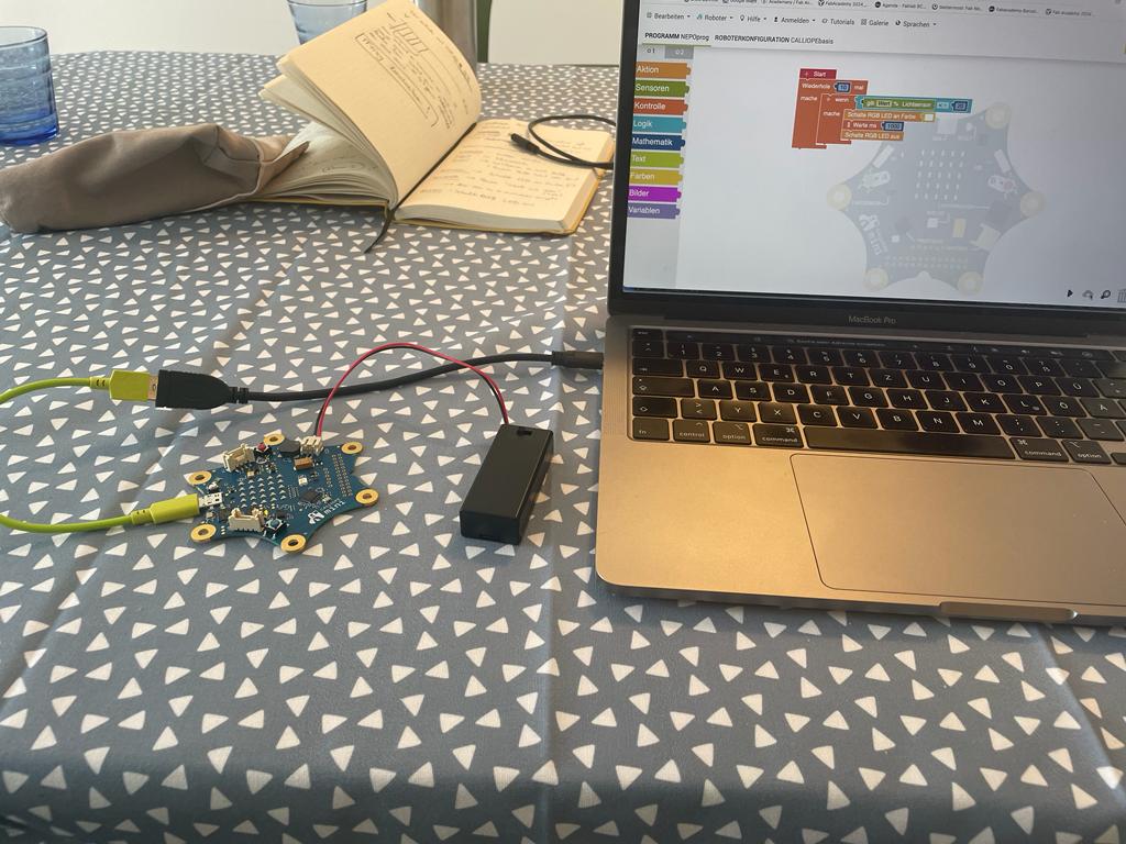
I explained the individual steps and we searched for the corresponding commands. First, we looked at the simulation. Afterwards, we connected the microcontroller to the computer and downloaded the program. Unfortunately, we always received an error message. However, we were able to find out that saving to the flash memory of the Calliope mini is possible. We placed the program at the first position of the flash memory and then played it. We then tested the function in a dark room with a flashlight and the night light came on when we turned off the flashlight.
Barduino
To work on our Barduino Board with Arduino IDE, we first had to install the board. I followed all the steps on the Barduino Documentation Page under the section Getting Started.
I had to complete the following steps, and it took a while to get started:
- PI opened the preferences menu: File/Preferences
- In the additional boards dialog, I added the following line: https://espressif.github.io/arduino-esp32/package_esp32_dev_index.json (I had to wait a long time until the download was finished, but it finally installed).
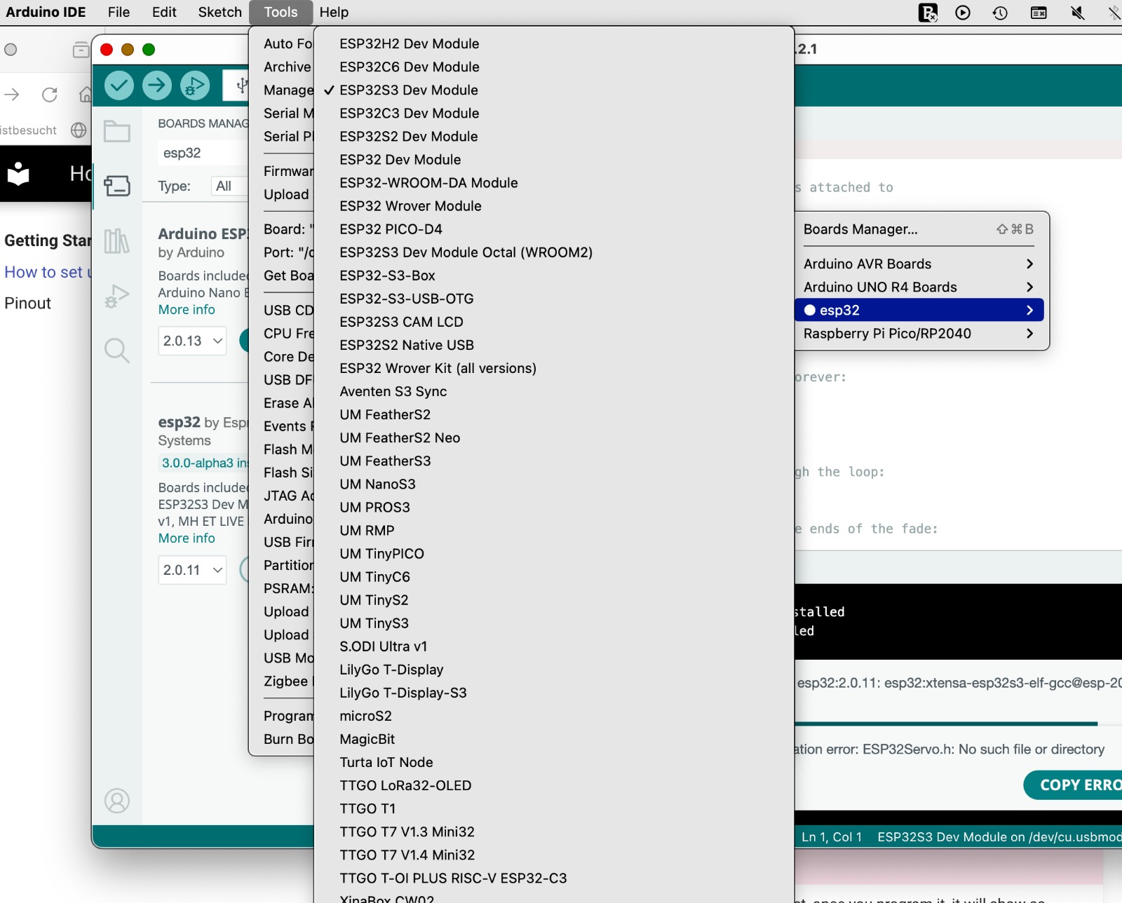
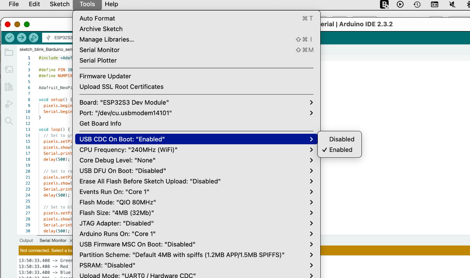
- After it was downloaded, I added the board by going to: Tools > Boards > ESP32 > ESP32S3 DEV Module.
- As recommended, I also changed the setting from disabled to enabled under: Tools > USB CDC on Boot
- Additionally, I selected the correct port using: Tools > Port.
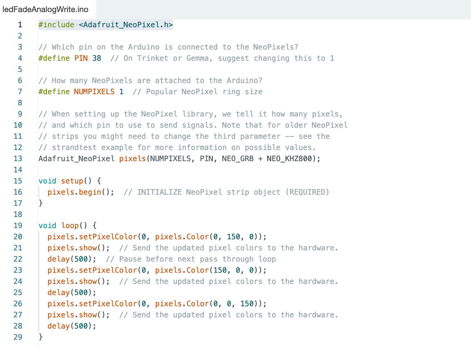
I then returned to the Barduino page and looked for examples. I downloaded the files and chose the one called "neoPixel." However, I had to integrate a library first. To integrate a library, I went to: Sketch > Include Library > Manage Library. I searched for Adafruit Neo and found the library, then installed it. After that, I was able to upload the sketch to my board, and the neon lights blinked.
Serial Communication
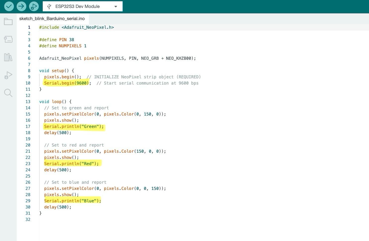
By adding serial output to my code, it is possible to precisely track what happens during the execution of the code. In my case, the Barduino board sends additional feedback via the serial interface to show which color is currently displayed. I have expanded the code with the following elements:
Setup:
- Serial.begin(9600);: This line starts the serial communication. It's important to set a baud rate here. This must be the same on the microcontroller and in the Arduino IDE.
Loop:
- Serial.println("Color");: This command sends a text message to the computer, displaying which color is currently shown. This is useful for debugging purposes or to check if the program is running correctly. In my case, it's also easy to see that it is working well because the LEDs are lighting up. But in other cases, it can be helpful when the code is more complicated and not directly visible.
It's important to select Tools > USB CDC On Boot > Enabled.
Quentorres
Since I had already integrated the board into the Arduino IDE at an earlier time, I was able to use it without any problems.
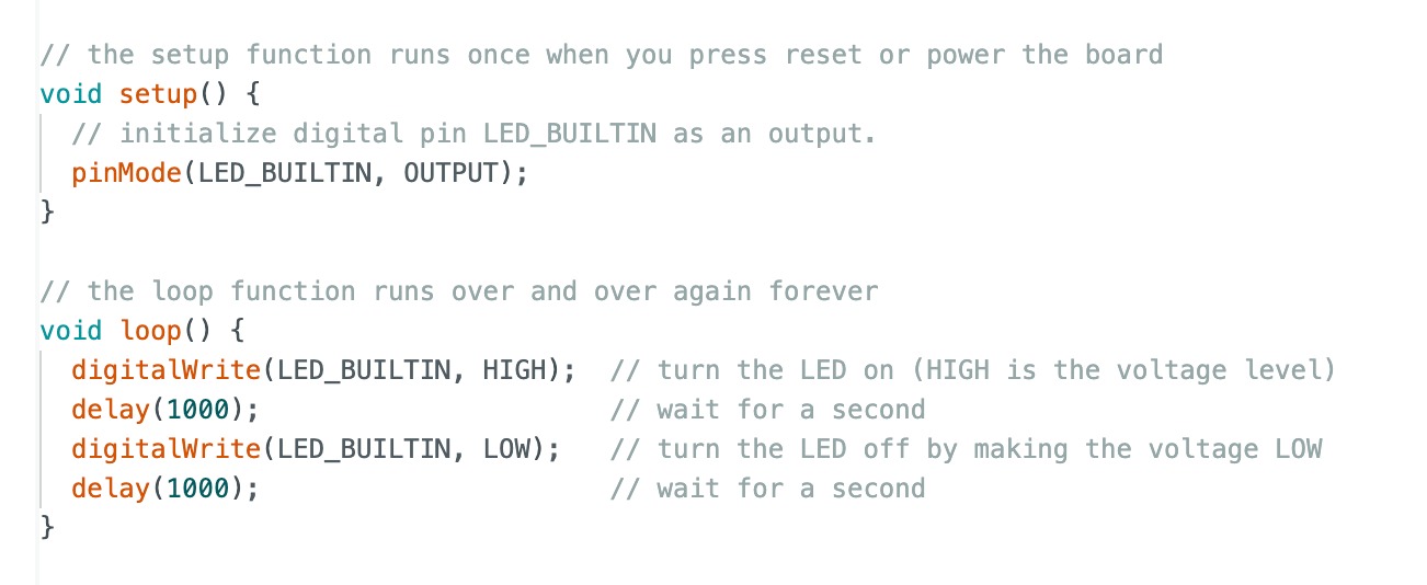
I then chose File > Example > Basics > Blink. I had selected this option once before, but only customized it with assistance, so it seemed like a good option to try it again.
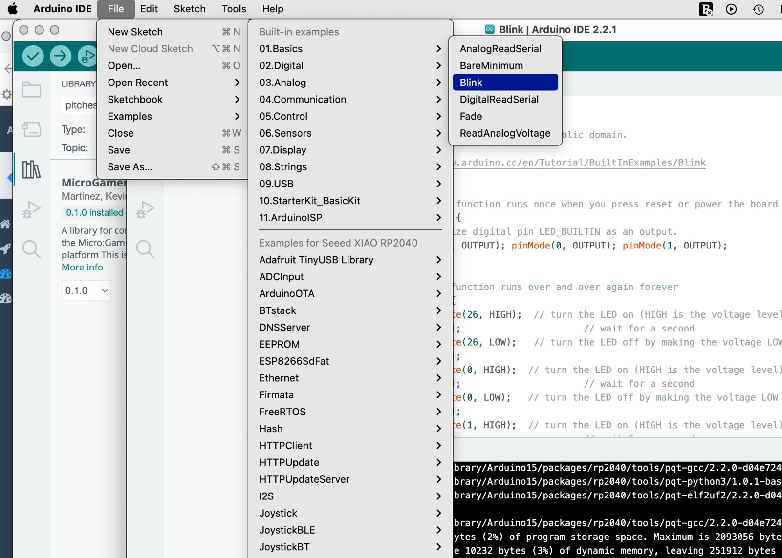
I opened the code and adjusted it so that the correct LEDs were selected and blinked one after the other.
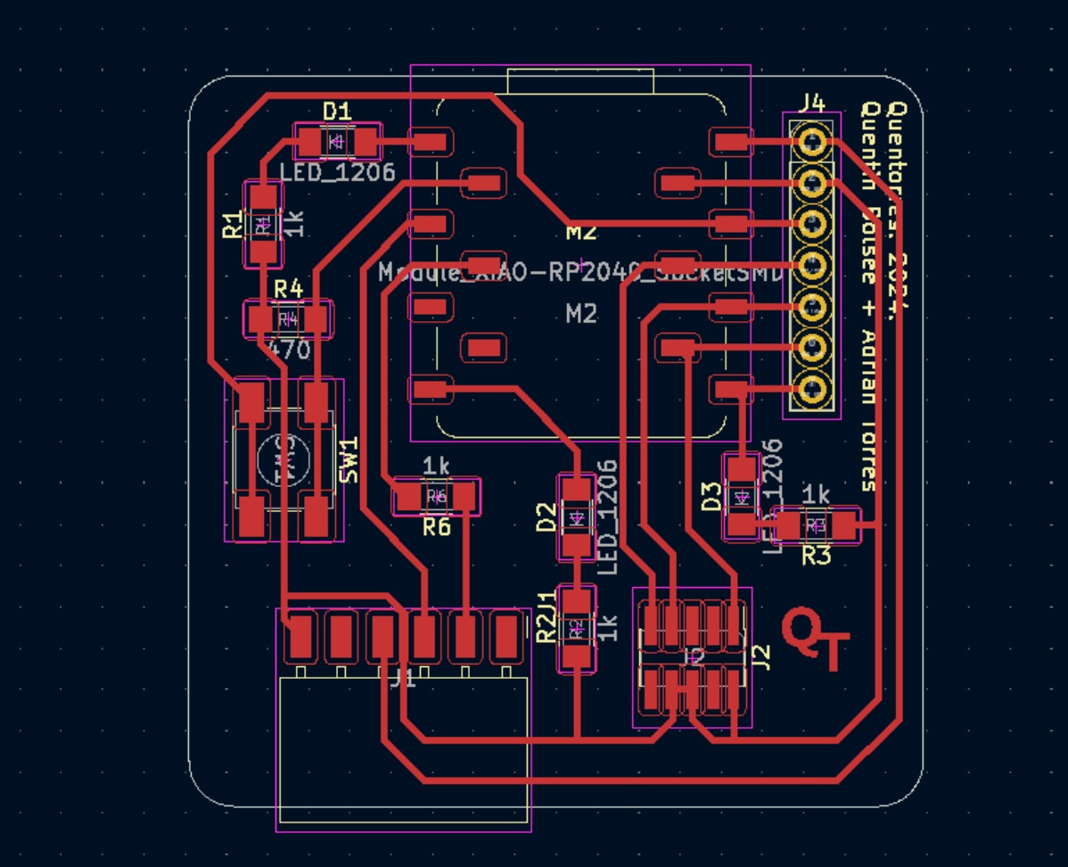
To change the code, I had to define the digital pins by replacing the placeholder LED BUILTIN with the corresponding pin number. To find out which pin is connected to which LED, it is important to know the circuit diagram. We had already learned this two weeks ago when we manufactured the board. I then replaced the placeholder LED BUILTIN with 26 according to the diagram and added two more pin modes, replacing the number 26 with 0 and 1, the pins of the respective LEDs.
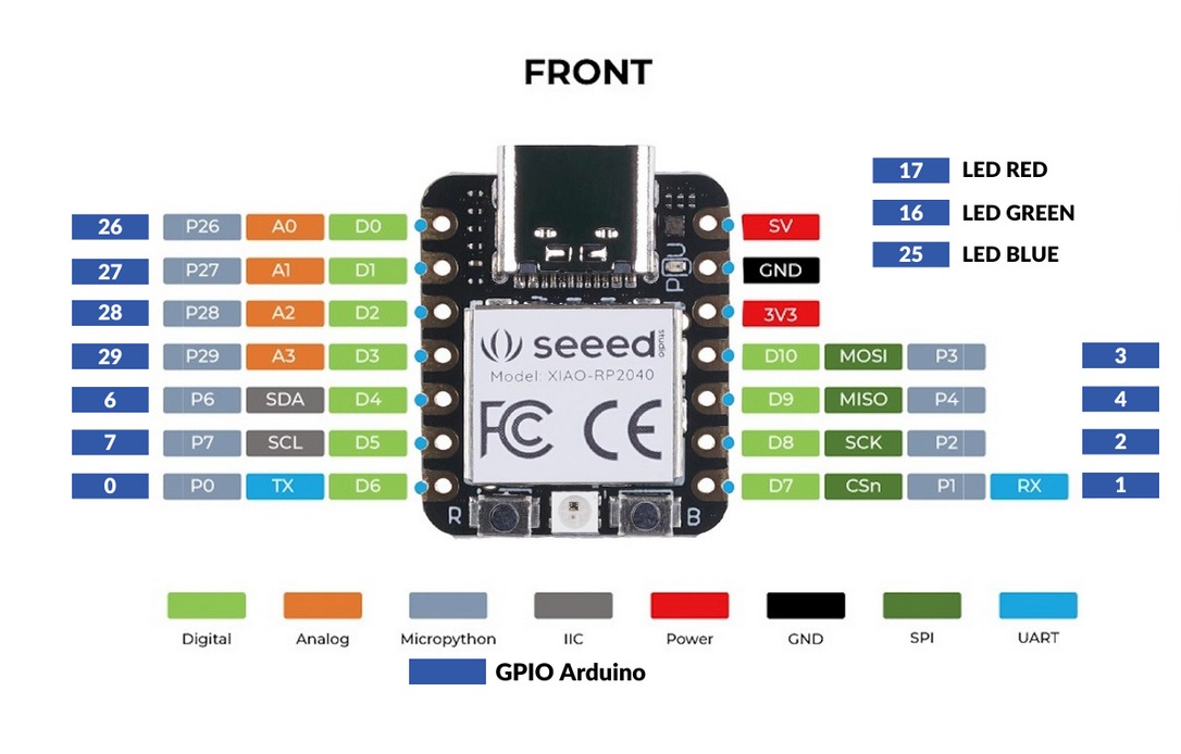
pinMode(26, OUTPUT); pinMode(0, OUTPUT); pinMode(1, OUTPUT);
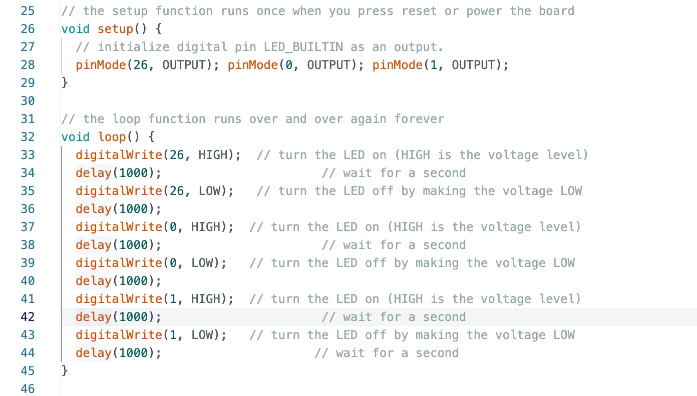
After that, I inserted what should happen in the further code. Since the LED should blink, a delay is also inserted. If this delay is not added, the blinking would be too fast for the human eye to perceive. The code then looked like this:
I downloaded the code to the board an the LEDs blinked.